SOLIDWORKS has an option for adding MBD PMI to your CAD model. The result is a digital file (SLDPRT/SLDASM) containing the GD&T, and other PMI, like bill of materials, etc., in a digital form in effort to move users to a paperless and more efficient dimensioning system. The concept of GD&T has always been ‘functional’. In other words, the GD&T is based on real physical features of the components.
Origin’s Checkmate can consume and re-use the SOLIDWORKS PMI, automatically generating inspection features based on the MBD PMI in the SOLIDWORKS DimXpert Manager.
THE DISCOVERY
In recent months, we have encountered SOLIDWORKS files that contain PMI reference planes. These reference planes are theoretical planes and not real physical features of the part itself.
From what we have learned, reference planes are used in SW PMI for two reasons. The two use cases are:
- As a non-measurable, non-physical feature as in the diagram (the intended use of a SW reference plane)
- As a direct replacement of a part face with zero-offset to allow the user greater control of the placement of the annotation.
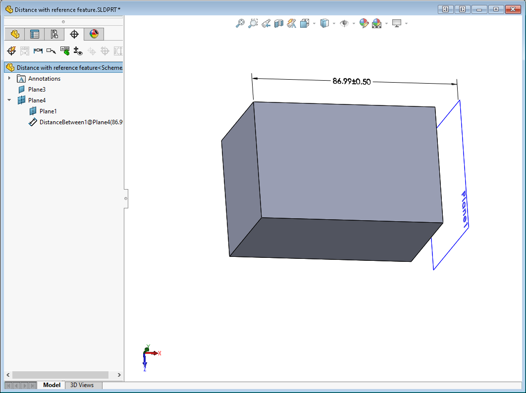
The image below illustrates a Distance PMI using the reference plane called Plane1.
THE PROBLEM
The SOLIDWORKS A.P.I. (Application Programming Interface) fails when trying to return the ‘name’ and ‘type’ of the reference plane. There is no direct method of obtaining the parameters (location and vector) of the reference plane feature (Plane1 above) from the dimXpert tree feature (Plane4 in the DimXpert tree above).
THE WORKAROUND
CheckMate attempts to work-around this missing direct link by looking at the location of the witness lines on the dimension call-out. CheckMate finds a reference plane in the feature tree that matches the location of a witness line and makes the connection that way. This method is reasonably reliable with use case #1. CheckMate makes a nominal reference plane in the CheckMate program at the location of the SW reference plane.
With use case #2 things are not so simple. Not only does the connection between the dimXpert plane and the feature tree reference plane need to made, CheckMate needs to discover the part face that needs to be measured. CheckMate does this by looking for a planar face with the same parameters as the reference plane. This isn’t 100% reliable.
The real workaround for use case #2 is simple. Do not use Reference planes when creating the dimXpert PMI. Instead of using a reference plane, use the actual face on the CAD model to create the PMI annotation.
 This Icon is installed on the Desktop and the